Electromagnetic compatibility is when a particular electronic equipment functions perfectly in a specified environment and it does not cause malfunction in any other equipment. In EMC considerations is both radiated and conducted energy therefore it has two aspects, emission and susceptibility. Nowadays electronic devices such as phones, laptop, tv, smart
home system operating in a small area, they are all prone to damage. EMC that is unfavourable can cause malfunctioning and reduced performance, or total failure of the system.
Real-World Application Scenario
In an average household, not one but several devices like the Wi-Fi router, mobile phone, microwave oven, bluetooth devices, etc are on, all these devices emit electromagnetic radiation. Nearby devices could be affected if not properly designed. A smartphone possessing weaker shielding may not work efficiently when placed near a microwave oven, owing to Electromagnetic interference, EMI refers to electromagnetic emissions from an electronic device that negatively affects the operation of other devices or systems. EMI includes both radiated and conducted disturbances from a device. In order to achieve reliability, engineers the devices to limit the electromagnetic radiation emitted and at the same time the device should not be disturbed by any outside influence. In devices such as smart televisions and wireless earbud systems, maintaining an optimal signal is an important
consideration.
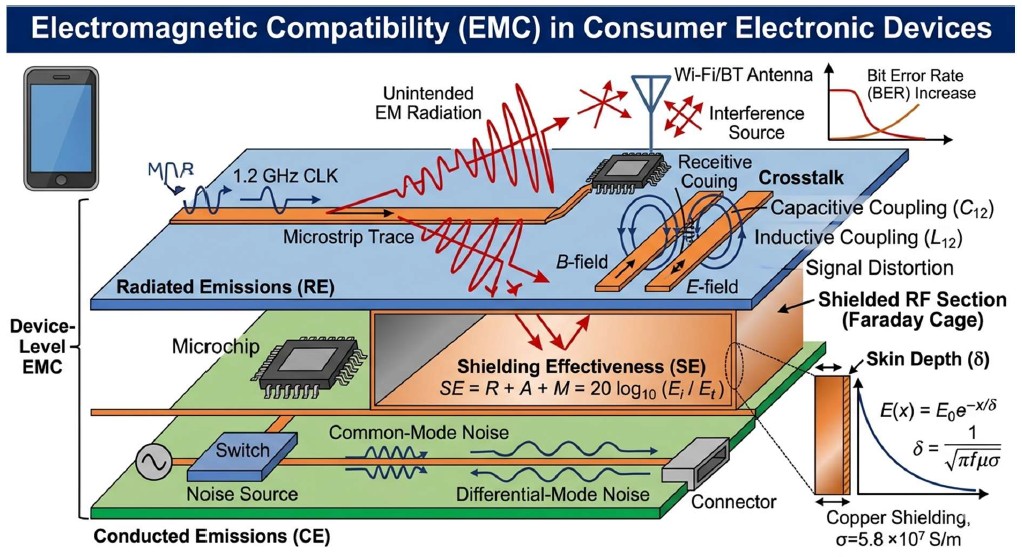
- Maxwell’s equations: These equations account for the way that moving charges and changing fields create the EMI that EMC attempts to control.
Faraday’s law of induction explains how a changing magnetic field from one
component induces an unwanted emf or noise in a nearby PCB (conductive path) trace.
Ampere’s law (with Maxwell’s correction) describes how high frequency switching currents in digital circuits produce radiated magnetic fields that interfere with wireless circuits.
Boundary Conditions:
When an EM wave hits a conducting surface, the boundary conditions for electric and magnetic fields require the tangential electric field to be zero at the surface. - It justifies the use of Faraday Cages and metallic coatings to reflect/absorb EMI which stops it from escaping the device or entering sensitive areas.
- Transmission Line Theory & Crosstalk: In high-speed digital circuits, PCB traces do not act like simple wires rather as transmission lines:
Impedance Matching: If the trace impedance is not matched to the load, EM waves mirror, causing ringing and increased emissions.
Capacitive & Inductive Coupling: These are the EMFT terms for Crosstalk. Energy transferring between parallel traces through electric and magnetic fields. - At elevated frequencies, which are commonly encountered in modern electronics, current flows only on the outer skin of a conductor. This increase in the AC resistance of wires and traces needs to be taken into account in the design of effective grounding and shielding for EMC purposes.
- Coupling mechanisms: Radiated coupling: EM waves travel through space and affect other devices. Conducted coupling: Noise travels through wires or power lines.