The modern systems of optical communications depend on the usage of low loss optical fibers with transmitted data encoded in the form of light modulations at terabits per second. At the physical level, there exists no single ray of light propagating through the optical fiber but rather, there exists a stable EM field distribution in space, which fulfills both Maxwell’s equations and boundary conditions on the fiber core-cladding boundary [1].
There exist two major classes of fibers used in practice. The first one is the Single Mode Fiber (SMF). It allows propagation of only one fundamental mode and provides a solution to inter-modal dispersion problems, which results in long-range connections including trans-oceanic and trans-continental links. The second class, the Multi-Mode Fiber (MMF) allows simultaneous propagation of many different modes due to its large core and is used for intra-facility communications and data-center interconnection.
An optical fiber is a cylindrical dielectric waveguide. The core consists of refractive index n1 and the surrounding cladding has n2 < n1. Light is confined by total internal reflection (TIR), which
occurs for angles of incidence exceeding the critical angle θc = arcsin(n2/n1). From an EM
point of view, the guided fields must satisfy the time-harmonic Maxwell’s equations in each region and match tangential E and H at the core cladding boundary [3].
For a z-directed propagating wave with propagation constant β, the transverse field components inside a step-index fiber obey the Helmholtz wave equation:
∇t² Ez + kc ² Ez = 0
where kc ² = n1²k0² − β² inside the core (k0 = 2π/λ is the free-space wavenumber). In the cladding
the field decays evanescently with decay constant γ² = β² − n2²k0². Guided modes
exist only when n2k0 < β < n1k0. Solutions to the eigenvalue equation in cylindrical coordinates yield the LPlm (linearly polarized) mode set, of which HE11 is the dominant fundamental mode.
The most important design parameter governing the number of guided modes is the normalized frequency V, also called the V-number or V-parameter:
V = (2π a / λ) × NA = (2π a / λ) × √(n² − n1²)
where a is the core radius, λ is the free-space wavelength, and NA = √(n2² − n1²) is the numerical apertures. The V-number encapsulates the interplay between fiber geometry, refractive-index contrast, and wavelength in a single dimensionless quantity.
For a step-index fiber, only the HE11 mode has no cut-off. All higher-order modes cut off when
V falls below a critical value. The LP11 group (TE01 , TM01, HE21) cuts off at V = 2.405 (the first
zero of the Bessel function J ). Therefore, the single-mode condition is:
V < 2.405 → Single-Mode Operation
Standard SMF-28 fiber (a ≈ 4.15 µm, NA ≈ 0.12) achieves V ≈ 2.1 at 1550 nm, safely below cut-off [4]. For MMF (a ≈ 25–31 µm, NA ≈ 0.20), V can exceed 40, supporting thousands of modes.
For a step-index MMF with V >> 1, the total number of guided modes M is approximated by:
M ≈ V² / 2 For a graded-index fiber with a parabolic profile (α = 2), this becomes M ≈ V²/4, halving the mode count and significantly reducing intermodal dispersion.
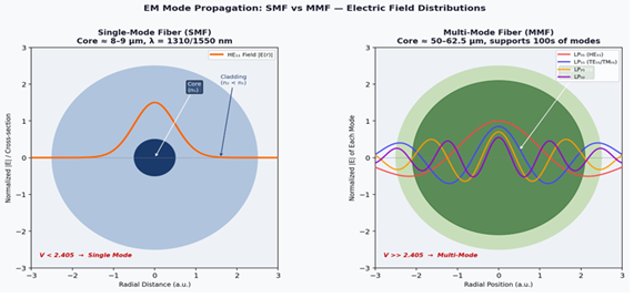
The radial distribution of the electric field in the two fibers is depicted in Figure. In SMF (left image), only one mode (HE11) exists, with a Gaussian-like shape localized in the core and having an evanescent tail outside the core into the cladding region. In MMF (right image), more than one LP modes can exist, each having their own characteristic oscillatory distribution.
The propagation velocity of each mode in a step-index MMF is different, i.e., vg = dω/dβ for various modes. Among all modes, the highest order mode propagates at the most oblique angle. Therefore, in comparison to the fundamental axial mode, its propagation distance will be larger. This causes pulse broadening or intermodal dispersion.
The modal delay spread ∆τ for a step-index MMF is given by:
∆τ/L ≈ (n■ ∆) / c
where ∆ = (n1 – n2)/n1 is the relative index difference and c is the speed of light. For a typical SI-MMF with n1 = 1.48 and ∆ = 0.01, the pulse spread in MMF is about 50 ns/km, which
is not good enough as far as chromatic dispersion is concerned as it has to be less than picoseconds per kilometer. Graded-index profile of fibers results in decreasing of ∆τ by factor of ∆/2, thus allowing using OM3/OM4 MMF for 40 and 100 Gb/s links.
There is no effect of intermodal dispersion in SMF; therefore, material and waveguide chromatic dispersion prevails. The typical value of D is equal to 17 ps/(nm·km) for SMF-28 at 1550 nm. Dispersion-shifted and non-zero dispersion shifted fibers allow shifting of zero-dispersion wavelength to low-loss wavelength range (1550 nm).