An alternative to traditional radio frequency (RF) links with high bandwidth and no need for a license is free-space optical (FSO) communication. FSO systems have the ability to achieve data speeds of more than 10 Gbps by utilising the unregulated optical spectrum (typically between 785 and 1550 nm). However, due to the very small beam width of the laser used in FSO systems, point errors are a major limitation. In contrast to RF waves, which radiate outward from an antenna with considerable divergence, optical beams are highly directional. As a result, while the optical directionality provides both security and efficiency of power, it also makes the FSO link extremely sensitive to pointing errors; that is, misalignment of the beam axis of the optical transmitter with the centre of the optical receiver.
Real-World Application Scenario: Satellite-to-Ground Links
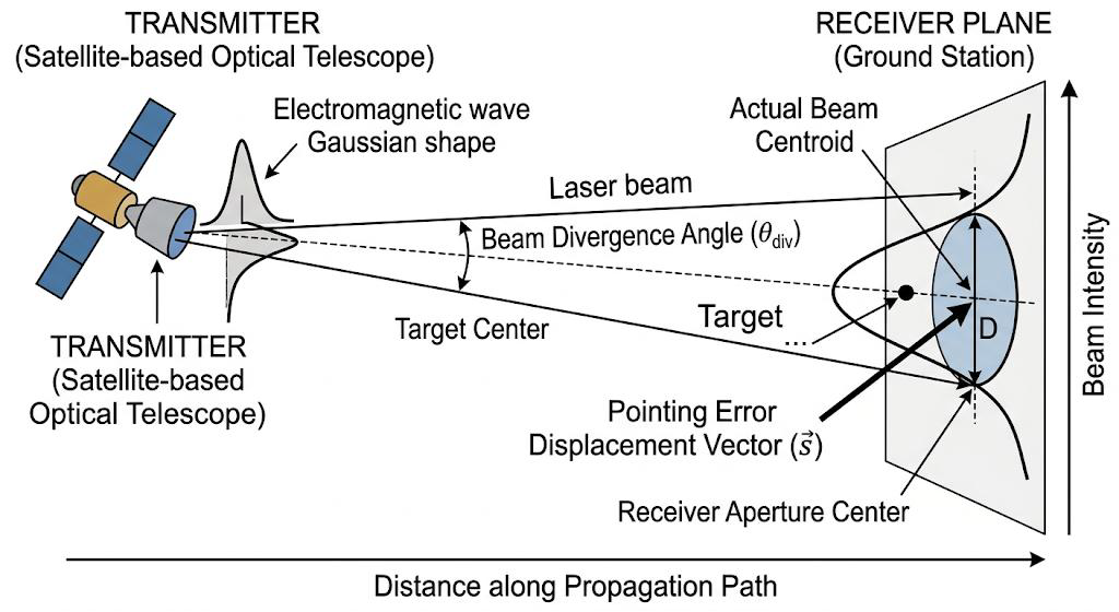
The most important application of Free-Space Optics (FSO) technology is between satellites in orbit and ground-based communications devices. The growth of low-earth orbit (LEO) satellite constellations (such as the Starlink or Kuiper systems) has created a compelling need for high-speed optical downlinks to Optical Ground Stations (OGS) from these satellites. In order to achieve this point-to-point communication between satellite and ground station, the satellite must maintain extremely precise milliradian alignment of the ground station as the satellite speeds toward it at approximately 7.5 km/s. Pointing Error is created by:
- Mechanical Jitter: Vibrations
within the satellite’s gimbal or reaction wheels.
2. Atmospheric Turbulence: Refractive index fluctuations that cause “beam wander.”
3. Thermal Expansion: Structural changes in the satellite or telescope housing due to solar heating.
To analyze pointing errors, we must apply fundamental EMFT principles:
- Gaussian Beam Propagation: In EMFT, A Gaussian intensity profile describes a laser beam, which can be modeled as a transverse electric (TEM) field. Unlike an ideal plane wave, the amplitude of the electric field of a laser beam decays exponentially as you move away from the optical axis.
- Irradiance (Power Density): The Poynting vector S=E×H defines the directional energy flux. In FSO, we focus on the time-averaged magnitude of the Poynting vector, known as Irradiance (𝐼), measured in 𝑊/𝑚2.
- Diffraction Limits: According to Huygens-Fresnel principle, the beam naturally spreads as it propagates. The beam waist 𝑤(𝑧) at a distance 𝑧 determines how much power can be collected by a finite receiver aperture.
Mathematical Analysis of Power Loss
The intensity distribution 𝐼(𝜌,𝑧) of a Gaussian beam at a distance 𝑧 and radial distance 𝜌 from the beam center is given by: 𝐼(𝜌,𝑧)=𝐼0(𝑧)exp(−2𝜌2𝑤𝑧2)
Where:
- 𝐼0(𝑧) is the peak intensity at the center.
- 𝑤𝑧 is the beam radius at distance 𝑧 (where intensity falls to 1/𝑒2).
When a pointing error 𝑠 (displacement in meters) occurs, the receiver is no longer at 𝜌=0, but at 𝜌=𝑠. The received power 𝑃𝑟 can be approximated by integrating the intensity over the receiver aperture of radius 𝑎. If the aperture is small relative to the beam size (𝑎≪𝑤𝑧), the fraction of power lost due to pointing error (Pointing Loss, 𝐿𝑝) is modeled as: 𝐿𝑝≈exp(−𝐺𝑡𝜃2)
Where:
- 𝐺𝑡 is the transmitter gain (related to the narrowness of the beam).
- 𝜃 is the angular pointing error (radial displacement divided by distance).
From an EMFT perspective, a pointing error shifts the peak of the Poynting vector away from the collector, leading to a catastrophic drop in the detected electromagnetic flux because of the exponential nature of the Gaussian profile.