Ultra-Wideband (UWB) monopulse signals are short-duration pulses with very large bandwidth, used in high-speed wireless communications, radar, and positioning systems. In the optical domain, UWB signal generation offers advantages such as low loss, immunity to electromagnetic interference, and the ability to integrate with high-capacity fiber-optic networks.
How It Works
One of the effective methods to generate UWB monopulses is by using an optical delay line structure.
- Input Light Source
- A continuous-wave (CW) laser or modulated optical carrier provides the initial optical signal.
- Splitting the Optical Signal
- The optical carrier is split into two (or more) branches using an optical coupler.
- Optical Delay Line
- One branch is passed through an optical delay line (e.g., a length of optical fiber) that introduces a controlled time delay Δt.
- Polarity Control / Phase Shift
- One branch may also undergo a π phase shift (180°) or intensity inversion using an optical modulator.
- Recombination
- The delayed and non-delayed signals are combined at an optical coupler.
- The interference of the two signals produces a monopulse-shaped waveform in the optical domain.
- Photodetection
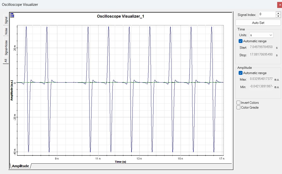
- When the combined optical signal is converted to the electrical domain by a photodetector, an electrical UWB monopulse is generated.
Why This Works
The UWB monopulse results from the constructive and destructive interference between the original pulse and its delayed (and possibly inverted) copy. This creates a pulse with a very sharp leading and trailing edge, resulting in a broad frequency spectrum, characteristic of UWB signals.
Key Features
- Tunable pulse shape: By adjusting the delay line length, different UWB pulse widths and spectral characteristics can be generated.
- Simple and cost-effective: Requires only passive optical components (couplers, fiber delay lines).
- Reconfigurable: Phase shifters and variable delay lines allow flexible waveform design.
Applications
- UWB wireless communications — high data rate, short-range links.
- Impulse radio systems — secure and low-power communications.
- Radar and imaging — fine resolution due to wide bandwidth.
- Optical signal processing — generation of high-speed electrical pulses using optical components.